I added an easy way to unplug and plug in the camera’s speaker. Unplug to connector.
Please do not read this as a criticism of Wyze. I like Wyze products. I am confident the recent camera speaker interface to an Echo Show is certainly not on purpose. I want to believe it’s an accident and will be corrected. But it also highlights the complexity or these products else, someone on either side would immediately know how to arrest the issue and it would not have lasted 24 hours. If it’s this complex to resolve, it could occur again. I am preparing not only for the fix, for the possibility it happens again. Just a drop of preparation since I can’t prevent it.
When it became mid-June, I opened a V3 and V4 and spotted where the speaker plugs into the PCB and unplugged it. Simple. It does require risking minor damage to the front bezel. It’s also going to lose part of his weather-resistance. And of course, void the warranty.
Yes, what I am doing voids the warranty. I am not going try and return one that I have hacked. But if fails after I have mod-ed it, I will eat the $30. Its not a $300 investment, just a $30 cost.
In this picture, you see several items. Top are these small 1.25mm small J2 male/female pigtails from another project. They just happen to be what I needed here. You see the bundle of male and female pigtails I got for $7.
1.25 mm JST 2 Pin Micro Male and Female Connector Plug
1.25 mm JST 2 Pin Micro Electrical Male and Female Connector Plug with 10 cm Wire Cable. It fits the Wyze speaker port on the back of the PCB. You can see the male and female end next to the penny. Small, eh?
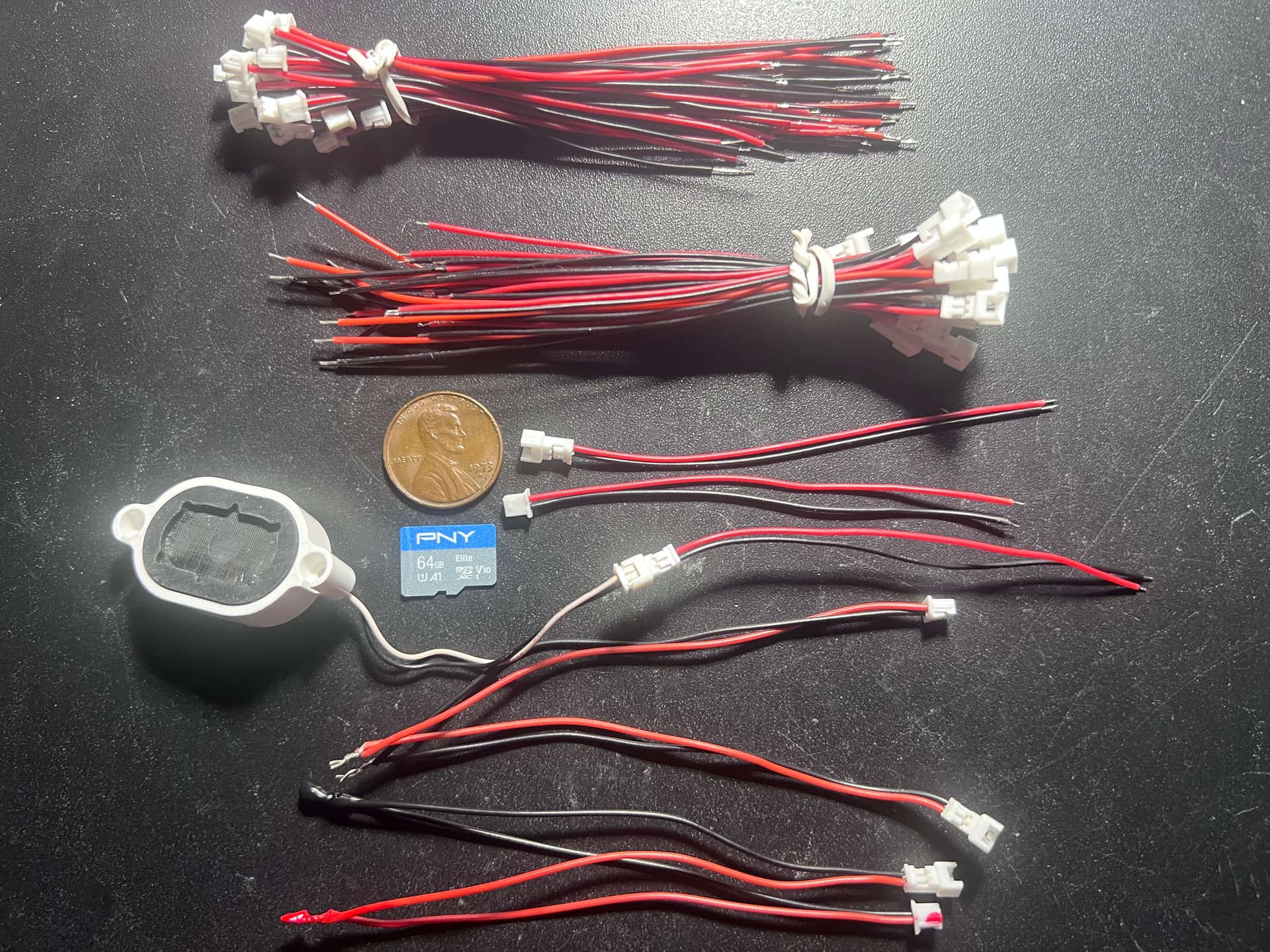
I connected a pair together to create an extension cable. A drop of solder. And too small for heat shrink, so dipped them each in thick paint to insulate them. In the picture, there’s two twisted together and one set soldered and dipped in the paint.

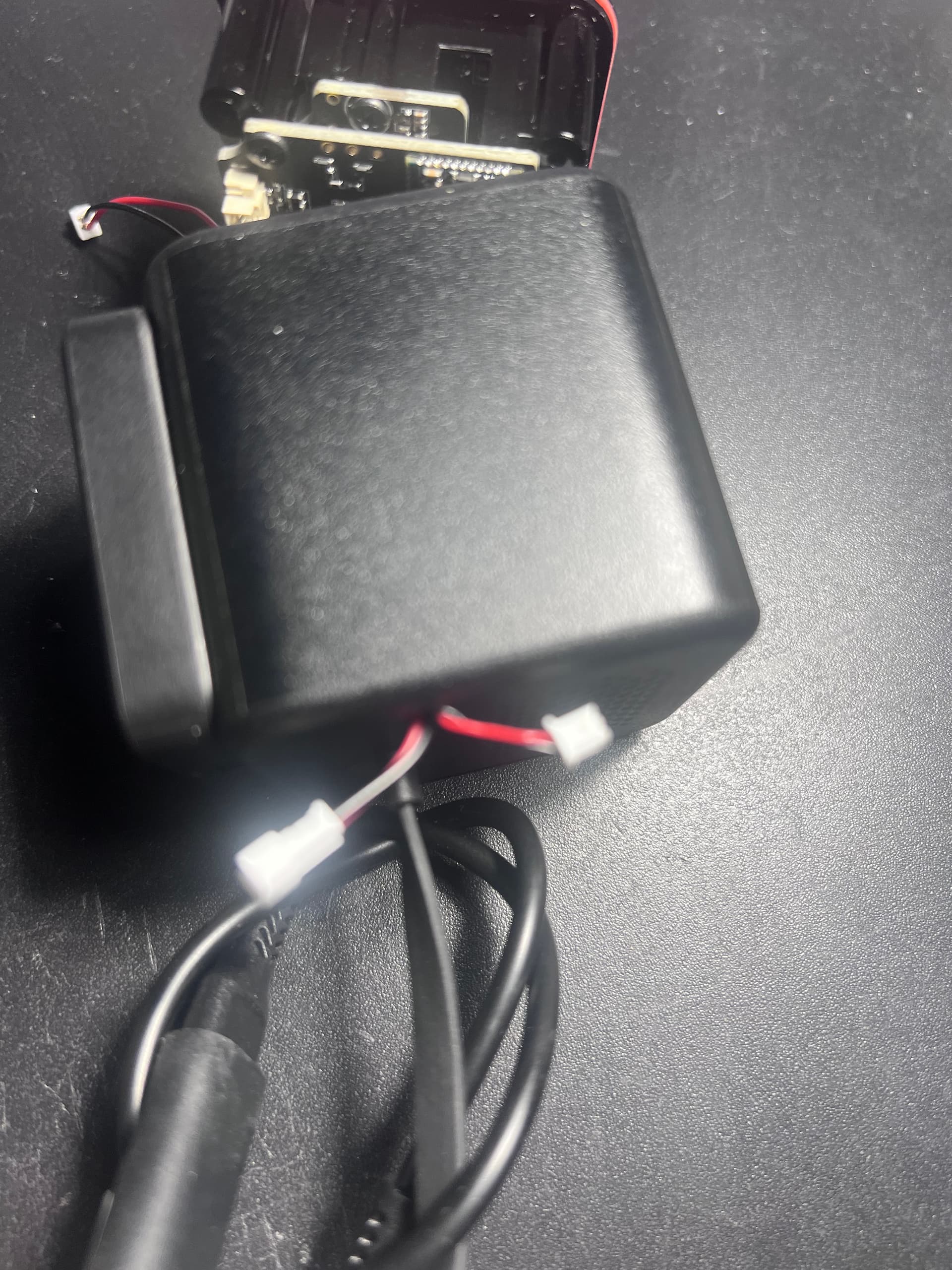
This picture is merely the V4 with the bezel removed.

This picture shows the red rubber seal around the groove at the front of the camera body. When working the body out of the case, be careful not to damage the red rubber seal.

In this picture, the screwdriver is pointing to the connector where I had unplugged the speaker.

The tip of the screwdriver tip is pointing to the hole at the top of a stem where the small screw is to hold the body in the case. Because of this stem/stalk, I drilled the hole 3/8 of an inch away from the corner. I picked this corner, because it’s the corner closest to the wire from the speaker. You see the red/black wire with white connector. The screwdriver shaft is covering where the wire connects to the speaker. I want maximum wire length available if needed when threading through the new drilled hole. Better view of drilled hole coming up.
I drilled a small hole in the back of the camera case and threaded the wire/connector for the speaker and the female end of the extension cable out the back. Now, a link to unplug and plug back in the speaker is convenient to me. These camera with this issue, are outside and hidden, but are not in direct weather. I don’t think this expose connection is a risk. Later, I can put a dap of silicone over it and seal them.

In this picture, the male end of the speaker wire protruding through the new hole. I started small and increased the drill size to find smallest hole, I could use to get connector through. The hole is 5/16. Snug fit for the speaker wire, first. Then when I added the new extension cable, I pushed the male end from the outside to inside, because the male end is smaller. Again, snug fit, but works.
In this picture, you can see the extension cable female end and the speaker wire male end. There is an extra ¾+ inches pushed inside. (Extension cable male end at opposite side of camera, ready to be plugged into speaker port on PCB.)

Pic merely confirming extension cable male end is connected to speaker port.
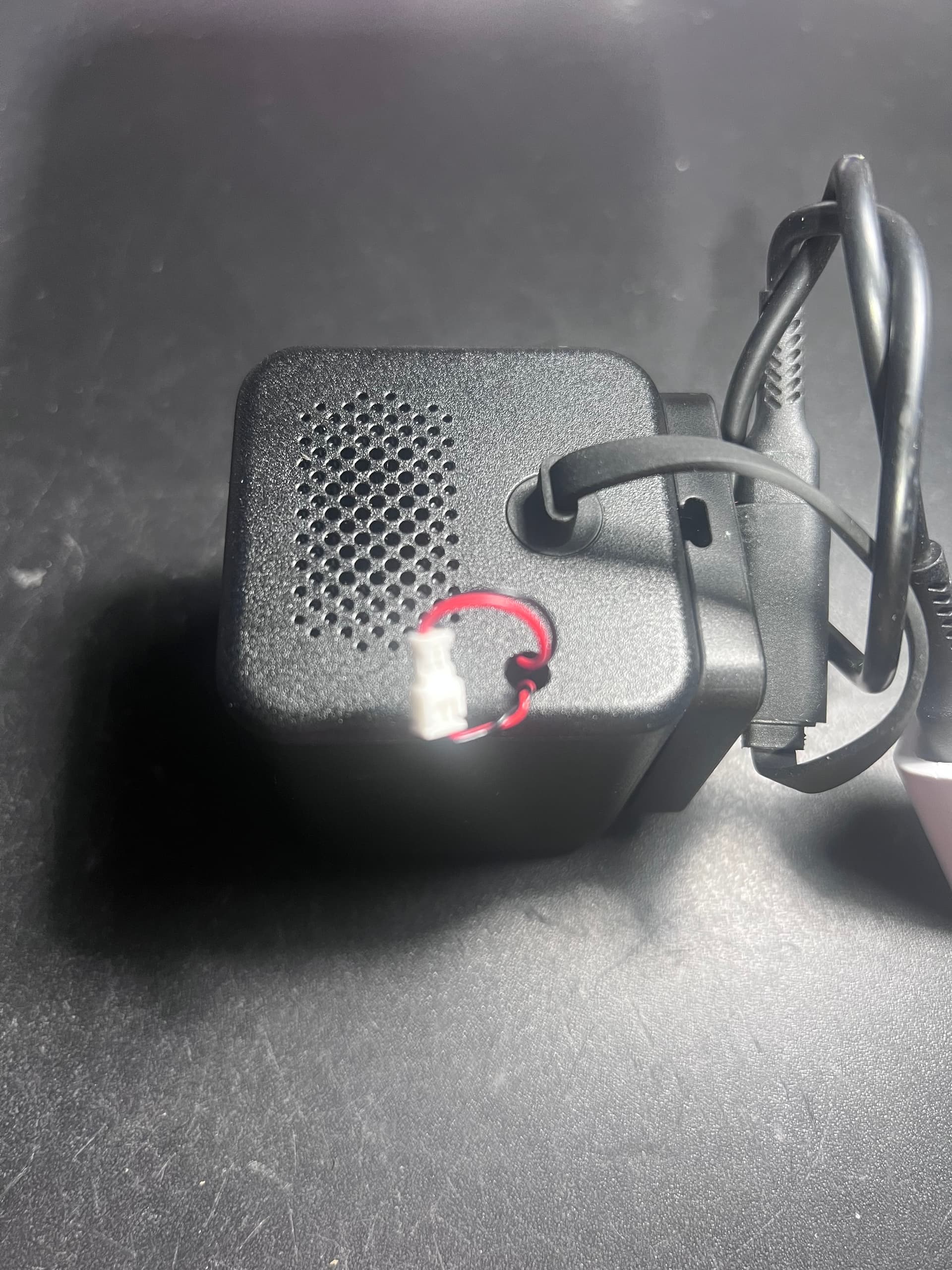
Picture shows Extension cable female end and speaker wire male in connected, engaging/ enabling speaker.
I took this opportunity to run a couple of tests. I plugged 5v into camera. Speaker is connected. I created a new Alexa routine to Show Camera on Echo 5. I added 10 iterations of the command string “Show this-cam on Echo 5” with a 5-minute cool down between each command. Schedule it to start in 5 minutes. And like clockwork, 5 minutes later, IMMEDIATELY, the Buzzing started. (Never had a chance to cycle to the second iteration of the command string.)
- Only takes one command string to trigger the buzzing.
- I disconnected the extension cable and speaker wire. Buzzing ceased. Reconnected and heard buzzing again. Disconnected, - no longer hear buzzing.
- Disabled the Alexa routine. Buzzing continues. We don’t stop and Alexa routine, simply by disabling it. If it was already running, such as based on a scheduled start time, it continues until its own end, even if disabled for future executions.
- Since the routine continues, it cycles past the 5-minute cool down before the next command string iteration. Once the 5 minutes expired, the next command executed, as expected. And the Echo screen refreshed to show the camera’s image, HOWEVER, the buzzing never stopped, paused or and did not interrupt itself and during the image refresh.
- During all this, the camera’s mic is still active. Right now, the routine is still running, the buzzing continues and I am close enough to both the camera and the show. I can hear the camera buzzing and the Echo show is sounding the buzzing because the camera’s mic is hearing it and sending it though stream to the Echo. I don’t think anyone has noticed this before.
- Interrupted the camera’s buzzing by removing its power. Not using the app, unplugged the power and back in. Power is restored to the camera. Its past time for the routine to have completed its entire cycle. Therefore, the routine did not automatically continue and did not send another command string to the Echo. The Show is not showing a camera image, its simply showing its Home screen. So, looks like unplugging power (this was not a app restart of the camera.) and restoring the power does not pick an existing or fresh command string to send cam image to Echo.
- Re-enabled the Alexa routine, and set the schedule for 3 minutes in the future. Extension cable and speaker wire are connected. Alexa announced “okay” to execute the routine. And routine started, buzzing started immediately.
- I interrupted the buzzing at the Echo. On all Echo’s we can swipe down from the top center to get a menu. On that menu is the Home button, to bring the Echo to his Home screen. Doing that while the camera was buzzing, stopped the buzzing.
- This Alexa test routine, I am using, has 10 iterations of the command screen “Show cam on Echo.”. So, I waited, for one of the 5-minute cool down periods between command strings. Once the 5 was up, Alexa announced “okay” and buffered the image and showed the camera image again and started the buzzing again. I waited about 1 minute and swiped the menu and pressed the Home button again. Buzzing stops.
- We can stop the buzzing at the Echo screen, but:
(a) it does not cancel the routine
(b), if another command string follows, the buzzing will start again.
How to open a V3 or V4
On both, check the front of the camera. The front is a bezel. It’s held in place with some thin double-sided tape. Careful, so you can reuse the tape. But if you mess up the tape, some black electrician’s tape will hold that side/corner in place too, and doesn’t drastically hurt the cosmetics of the cameras.
IMPORTANT: REMOVE the SD CARD. IMPORTANT.
Using a blade, pry up and get a toe-hold on a corner or side of the bezel. There’s no snap, just tape, so, slip it under the edge and pry up a little, sliding along to work your way around. Don’t lift too high, you don’t want to warp the bezel, 'cause that will make it less likely to lay flat when you put it back on.
The outside case of the V3/V4 is simply a cube case with one side open. And includes a small hole in back for the pigtail.*
Bezel removed. There are three round screw holes and a small square hole - (ignore it). On the V3, you can put use a small blunt tipped Phillips screwdriver and remove the screws. On the V4, there’s white soft 2mm pads, (I guess), to protect the holes? Use tweezers and put them out. (Not necessary to put them back in.) Or a thin awl and pry them out. Remove the three screws with a blunt ended small Phillips screwdriver.
SAY AGAIN: IMPORTANT: REMOVE the SD CARD. IMPORTANT. Else, you will regret. Top of the SD Card will prevent the camera body inside from moving forward.
There’s a red rubber seal surrounding a grove around the lens face plate of the inside camera body. While not critical to performance, it’s going to keep water and dust out. Don’t mess up the red rubber seal.
Using a thin screwdriver for example, rotate around the three screw holes wedging the screwdriver against the inside of the holes to work the camera body forward and out. It likely will take 6+ cycles around the three holes to get it moving and out. Don’t pull it all of the way out.
Once you have the camera body loose, you can see it’s a frame with PCB, lens** and small connectors, From the top of the camera, it’s easy to see past the camera body that the speaker mounted in a white plastic cover. Note the wires and trace them backwards to the front so you can see where it connects. Just grasp the connector and wiggle it out. You are done.
Best to try and put the bottom of the camera body back in the front opening first, over the lip of the case bottom. The SD Card drive sticks up almost enough to make it obstruct the return of the frame to the inside of the case. Once you get the bottom over the lip, likely the camera body will pop in.
Put the screws back in. And replace the bezel. If it doesn’t fit tight, a little tape will help around the bezel.
*If you choose to go deeper into the removal. You can remove the pigtail. Disconnect it from its connector. Grasp it by the rubber at the outside hole and give it a soft half turn. It’s a slotted hole and the half turn allows you to ease it out.
**If you decide to break the camera body down further, the front and back PCB’s are held together by a couple of screws. Don’t take all out without studying where the go first. Leave the two in that hold the base of the lens housing against the back board. You can remove it later if you must. And notice, there’s some clear silicone glue on the lens threads. Using a small blade or awl, scratch the glue off the treads, then you can unscrew the lens without damaging anything.