Hello @WorldwideDave and others.
Eversince the Wyze V1 camera came out several years ago issues with aimng the cameras through windows to the dark outside from lighted inside rooms arose. The following pictures cronical how the black box on the window came to be in the developement of glare reducing approaches.
The picture below is of an early cardboard sq tube glare shield using a free library printed attachment collar. A spreadsheet was made avaliable to generate the patteren shape dimentions required for any combination of horizontal and vertical aim angle values. There were also sq wood tube shields that could be cut to the aim angles with a table or chop saw. These are very good at blocking glare from poluting the camera’s field of view. On the downside, aim angles beyound 30° left or right of straight ahead introduced field of view restrictions.
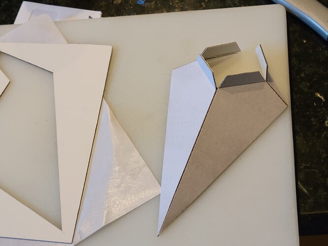
In the picture below the attempt to reduce field of fiew restrictiond resulted in the sq pyramid kite style of camera holder glare blocker. The intricate geometry was handled with a spreadsheet that provided the pattern shape based on input values of the horizntal and vertical aim angles needed at its intended location.
The picture below illistrates a library 3D printed version of the sq tube glare shield with a V3 loaded in it. In this light shield and the previos ones shown the camera’s base is removed to provide a lighter more compact form. The brim around the sq tube provides some glare blocking for narrowly spaced double paned windows, and tape area for its attachment to a window. An anchor that helps keep the cord tidy is also shown.
This is my 3D printed version of the paper one shown 2 pictures above. This was my first 3D printer and I inadvertently picked the wrong color reel. On the positive side this color would definately show up in any field of view restrictions.
The picture below is the camera’s field of view through the orange glare blocker.
, shown directly above Not a hint of orange around the image’s perimeter. Hence no view restrictions.
I went back to the sq tube type in the picture below and modified it to accommodate the full section of the V3. This version did not require the removal of the camera’s base prior to loading in the camera. It has the same field of view restrictions at aim angles larger than 25° as the previous ones shown. It is fairly clean and compact looking, especially if a cord anchor was attached below it.
All of the 3D-printed camera holders/glare shields above are fixed-aim angle devices. To modify a horizontal aim angle another holder would need to be printed or an adaptor device added to it to alter the camera’s aim angle. The next three pictures below show an adaptor used. Not only does the riser alter the aim angle of the attached device, it reduces the camera’s view restriction. These adaptors are available from 0° to 10° in 1° intervals.
All of the 3D printed fixed angle devices described above required providing links to hundreds of separate STL files, one for each combination of horizontal and vertical aim angles in 5° intervals.
Below are some early adjustable aim glare shield approaches.
The articulated linkage version is shown below. This device is highly adjustable in its aiming abilities. It is to me somewhat ungainly looking and it needs a glare shield. Placing a box over it would block glare and its ungainly appearance. One could also tape a swatch of WUJI LP SATIN SOLID BLACK cloth from the JOANN fabric store over it. This cloth is light in weight and will totally block inside room glare.
My cone version of an adjustable glare shield is shown below. The camera has a semi-spherical belt around it that allows spherical movement within an arrangement of plastic receivers for it. This ball-joint action works great but I miss-designed it, and as a result, has limited aim adjustment. A rubber band has to be placed in the circular groove of the receiver to provide sufficient friction to maintain the aim direction. It is a bit bulky looking.
Now for the window box shown below: This is not very pretty looking but it is very adjustable when the box is temporarily removed. To clean up the appearance of this arrangement, I would refold the perimeter window mounting flanges inward (out of sight). The box would be repositioned to cover the window plate of the camera support bracket and the box’s mounting tabs would be hidden inside the box.
The best solution to window glare is to place the camera on the outside surface of the window as was stated in your response to me. The flat ribbon USB camera power cord is only 1.6mm thick and I suspect that a lot of operable windows have enough working clearance to accommodate this thickness. In the picture below I used a pocket knife to slowly and carefully remove one side of the outer sheathing from the power cord. The exposed individual wires, each with its own sheathing measure 0.93mm Ø. It should be easier to find enough working clearance to accommodate 0.93mm.
Another approach would be to get a round power USB power cord instead of the flat ribbon one. My round USB cord is 3.04mm Ø, which is less than 1/8". So a 1/8" hole would need to be drilled through some part of the window frame or even the glass (with a diamond-coated drill bit). The USB wire would be cut poked through the hole and spliced back together on the inside of the window. Place some caulking to seal the entry point of the cord.
Maybe a helmet would need to be placed over the outside camera for additional weather protection?
I am working on another idea for an adjustable window-mounted glare shield.
Victor.


