Wyze cam duo. Wired

I have had the wyze cam dup for 2 months. it works great but I’ve been using battery for a while now. Ive tried wiring it. connectors on the back seem ok. I do seem to have power going through it.

Ive wired the chime with jump cable.
Jump cable going to the trans to front. I had to disconnect the rear doorbell..else i was getting a buzz

The camera doesnt seem to get any powet going into it.

Welcome to the Forum, @kidchuckle! :wave:

I’m gonna start by saying that I do not have any hands-on experience with Duo Cam Doorbell, but I’ve done extensive troubleshooting with my own Video Doorbell v2, which is a wired-only (no battery) doorbell. I’m also not an electrician, but I feel comfortable doing some DIY electrical things.

I’m confused by a couple of your statements:

I’m not quite sure what you mean, because those seem to directly contradict one another. What additional detail can you provide to clarify what you’re experiencing?

Also, knowing the answers to some of these might be helpful:

  1. What did Wyze Support say when you contacted them?
  2. What’s your transformer rating?
  3. What’s your transformer’s actual output? In other words, have you tested with a multimeter? If so, then where/what have you tested, and what were the results?
  4. Your mention of disconnecting your rear doorbell makes me think you have a chime box with FRONT, TRANS, and REAR screw terminals. Is that correct? If so, then do you want to be able to have both doorbells connected and able to ring your home’s built-in chime?
  5. Have you considered installing a Chime Controller? That’s something I’d consider installing if I had a wired rear doorbell and wanted to reconnect it but not have it buzz. If you correctly install one of those to the FRONT and TRANS terminals instead of the jumper wire, then I would expect that to solve the buzzing issue and allow both doorbells to ring your home’s chime.
  6. Are you certain that your chime box was wired correctly before you started? If you’re dealing with FRONT, TRANS, and REAR terminals and had regular “dumb” doorbells that were working before you ever installed Duo Cam Doorbell and wired it into your system, then I would guess that it is, but it’s something else I’d want to check just because of my own experience.

If you can answer some or all of those questions, then that might help others in the community get a better handle on your situation and provide some guidance.

thanks. Sorry… i should have written more clearly.
thanks for the fast response.

I can detect theres voltage from the doorbell wires.

but as far as the wyze cam itself,the power doesnt seem to be charging the camera/battery from the wires.
No lights are on the battery.

I like the doorbell, just wish i could get it working in wired mode

I cant tell its the way ive wired the chime.
theres a tran, rear and front.
I hooked up the jumper wire from the front to the tran.
with the original wires still in place.
except for the rear( it was causing buzzing and random rings from my old chime)

1)I haven’t contacted them yet. I thought I would try the forums first. Thanks for your quick response by the way.

  1. Good question I only have a ac voltage detector.

  2. Unfortunately I’m not very electrical savy. I might have to purchase one.
    I was hoping the installation would be far less complicated. I cant say I have much electrical experience.

  3. Yes that’s correct. Trans, front, rear.
    I don’t really need the old chime to work. I’m fine using the Wyze chime…
    Especially the rear doorbell. I don’t really need it… its only when my kids use it, to trick us looking for them at the front or rear doors.

  4. Is the Chime controller only for wanting to use the original chime box sound? I don’t really need to. I rather just get the wyze duo cam powered and charged.
    Is the jumper wire sufficient enough, just for the charging?

  5. Yes the original chime was working. Our front doorbell was a little rusty, so it wasn’t consistent but it did make the chime work sometimes. And the rear doorbell worked consistently.
    I do see power going through it using the voltage detector.

Thank you again for your detailed feedback/questions.
I appreciate your help tons!

You’re welcome, and no apology is necessary! I saw your reply earlier today and would’ve answered sooner, but I needed to warm up my brain and get some coffee in my system before formulating a response, and then some other things jumped in the way. Here goes:

  1. You’re welcome again. I’d consider opening a ticket just so they’re aware of an issue in case there’s a problem with the unit. As long as you bought it directly from Wyze or an authorized retailer and haven’t done anything to void the warranty, it should still be covered.
  2. Is that like one of those non-contact voltage testers that looks like a pen or something else? When I ask about the transformer’s rating, what I’m wondering is what the transformer actually says its output should be. (Sometimes the first step in figuring this out is locating the transformer itself. Mine happens to be in a mechanical/storage room in the basement, on the same circuit as the furnace, but yours could be anywhere.) In my non-electrician’s experience, this is usually stamped or engraved on the housing and should show you two numbers: the voltage (expressed in volts (V)) and the apparent power (expressed in volt-amperes (VA)). As an example, see the picture in the Help Center’s Chime Compatibility Check article, which shows “16V 30VA”. Depending on which source you consult (Wyze’s own documentation is inconsistent) Duo Cam Doorbell wants to see either 10-24 V or 16-24 V and ≥10 VA from the transformer. I would guess that there’s a product sticker on the back of the unit that tells you what its AC power requirements are. (What I have powering my mechanical chime and Video Doorbell v2 says it’s rated for 16 V, 10 VA.)
  3. Like I’ve said before, :warning::high_voltage:  I am not an electrician.  :high_voltage::warning: I enjoy learning and troubleshooting these things, though, and my time with Video Doorbell v2 and other doorbells has definitely been a learning experience. When I asked about output, I was talking about measuring it with a multimeter. That was one of the first things I did (measuring voltage at the old “dumb” doorbell button’s location) prior to installing my Video Doorbell v2, so I knew that I had adequate power there. (Incidentally, I’ve routinely read >18 V AC when I’ve checked my 16 V transformer, and I understand that this is normal.) I’ve been using an inexpensive multimeter and a set of test leads from Harbor Freight for years, and those have served me well. The additional test leads aren’t necessary, but they’re convenient for clipping onto the multimeter probes and other wires or terminals so that I don’t have to hold that all together while I’m adjusting controls on the meter or taking notes or pictures.
  4. Thanks for confirming, and the photo is helpful! :+1: That wasn’t what I expected to see, but I don’t yet know why the jumper connection you made wouldn’t accomplish what you want. (In other words, I think it should be working if the wiring was correct and as expected before you began.) Knowing more about the transformer and what its power output is should fill in some blanks, I think. Is that some kind of digital chime? Mine’s mechanical, similar to what’s shown in the Chime Compatibility Check article.
  5. Yes, the Chime Controller is what you’d use if you want the new doorbell camera (and the old rear doorbell button, in your case) to ring the home’s existing chime. If you don’t want to use it, then the jumper wire should allow you to bypass the chime if you’re confident that it’s wired correctly. If you know for certain that the FRONT and TRANS terminals had the correct wires before you started, then even just disconnecting those wires from the chime’s terminals and connecting them together with a wire nut should close the loop and provide power to the doorbell. This is why I’d be inclined to test things for myself, though, to know that the connections were correct and that you’re getting adequate voltage at the Duo Cam Doorbell’s location. (Again, this is something I learned as I described in my link from #6 in my earlier post.)
  6. That’s helpful to know that the chime was working before you started. I’m still curious about what your voltage detector is and if it’s just giving you yes/no answers but no actual measurement.

I realize that my responses can get long-winded, but I hope that this is helpful information and that it makes sense. I enjoy problems like this. They make me want to troubleshoot in person but force me to think through what to ask and how to ask it as I try to fill in my mental gaps and try to understand the problem.

Feel free to hit me up with additional questions or let me know when you have an update.

Sorry for the delay. Man you’re so quick in replying and detailed follows ups!!!

  1. I’ll contact now!

  2. I do have contactless voltage testers. I can confirm there is power. Unfortunately I don’t have one that tells me how much voltage.
    I’ll have to try to look for the transformer. I have no clue where that might be… and the wiring my house seems a bit odd. Some things feed into a old security control box… I don’t know if that might complicate things.
    Oh wait. when you say the transformer. are you refering to the “TRANS” on the doorbell chime?

3)I might have to get a multimeter to test how much power

  1. thanks for clearing that up…

  2. I’ll disconnect those old wiring and tie them up and just leave the jumpers together.

  3. yeah it only gives a yes/no unfortunately no measurement. I should try to get one then!

No I do appreciated the detailed message… it helps me understand things a bit more. I’ve been reading the forums and trying to find videos but I’ve been scratching my head the last while.

Thanks again! I’ll try to follow up hopefully in a week. I’ll have to get a multimeter find out my results.

Thanks again!

No apology is necessary. I have plenty to keep me busy. You do things in your own time.

  1. I think that’s a good idea just in case the doorbell itself has a problem. If Support thinks there might be a problem with the device after having you do some troubleshooting and you can document that you bought it directly from Wyze or an authorized retailer, then they’re usually pretty quick to replace it. If that happens, then even if you don’t use a new doorbell at least you’d have a spare plus a replacement battery.
  2. Going back to the original post, this is why I’d want to test for voltage so we know that the right wires—I imagine you have one black and one white at the doorbell camera’s actual mount location—are actually showing adequate voltage across them. Locating the transformer can be tricky, and it can be anywhere in the home. I’ve seen other Forum users post about transformers in attics or closets or directly attached to the side of a breaker box. I’ve also seen YouTube videos showing transformers in the wall directly behind where a home’s chime is mounted. It may not be completely necessary to find the actual transformer, but it’s probably good to know where it is, and that might make solving this easier. I installed a wired Arlo video doorbell at my sister’s house a few years ago (because that’s what my brother-in-law had bought), and I still have no idea where the transformer is in their house, but I tested the voltage at the original doorbell switch’s location and so knew it would provide adequate power. Even if I knew where that transformer was and what its rated output was supposed to be, I still would’ve tested because I have the tool and testing is easy and gives me real data and confidence about proceeding.
  3. I picked one up before I understood how to use it, because it was cheap and seemed like a cool thing to have. (I think I had a coupon, too.) Since I’ve learned how to use some of its functions, I’ve found it to be very helpful in troubleshooting and tracing circuits when I’ve had to do other things, like replacing outlets (determining which upstream outlet feeds which downstream outlets on the same circuit so I know where to place GFCIs and where I can use regular non-GFCI outlets) or switches (determining which box in a 4-way setup actually has the “hot”/live coming in so I know where to place a single smart Wi-Fi dimmer and leave the other two “dumb” switches intact). It has been a tremendous help in troubleshooting my own video doorbell issues, too.
  4. You’re welcome.
  5. I’m not sure what you mean by this. If I interpret what’s going on in your photo correctly—and if the wiring to the chime was all correct when the top white wire was connected to the chime’s REAR screw terminal—then in order to supply power to the Duo Cam Doorbell electricity needs to flow from the TRANS wire to the FRONT wire to get to that part of the circuit. That’s what I meant about connecting those two wires together with a nut instead of using the jumper. The way the photo shows the jumper installed should already be providing that electrical pathway. I was just mentioning an alternative means for bypassing any connection to the chime itself. I hope that makes sense.
  6. Like I said, I think it’s a good tool to have if you’re going to tinker with electrical things, and I’ve been able to accomplish what I’ve wanted without buying an expensive tool.

No, I’m talking about the actual device that is somewhere in your house but connects to that TRANS terminal on the chime with a wire, similar to what’s illustrated in the diagram on the left in this part of the Chime Controller Installation Guide. Like I linked above—and will repeat here :backhand_index_pointing_right:the transformer itself is a separate device that’s converting your standard residential 110-120 V AC to the low-voltage (probably somewhere in the 10-24 V AC range) AC needed to power the doorbell. I hope that makes sense and the links are useful.

Note that the illustration I linked above shows a diagram for a single-doorbell installation, so it differs from what you have. In that picture, the single green line is representing two of your three black wires that come together in your chime box and are connected together with a wire nut. The red line is the black wire coming from the transformer and (presumably) connected to your chime’s TRANS terminal. The orange line is the white wire coming from your video doorbell’s location and (presumably) connected to your chime’s FRONT terminal. If that doesn’t make sense, then I can try drawing a picture more specific to your setup.

What chime (brand and model) do you have? That might help me to better understand what’s going on, too.

Let me know if you have other questions or if I need to try to clear up anything else.

Woah lots of good info.

I managed to get a multimeter… and had a chance to take a reading.
I think the powe maybe way too low.
Im not sure if Im doing this right.

looks like the power is too low?

i may need to find the transformer.
thanks again for your help!


1 Like

i think i found the transformer as well.


i tried using the multimeter right on the transformer as well.

i opened my circuit breaker. After watching a few videos to just have a look on how difficult it might be to swap out the transformer.

It looks like it might not be too difficult.
just cut the power to the house and swap wires.

1 Like

Hey! New toy! :+1:

Nope, but we can fix that, and the pictures are very helpful!

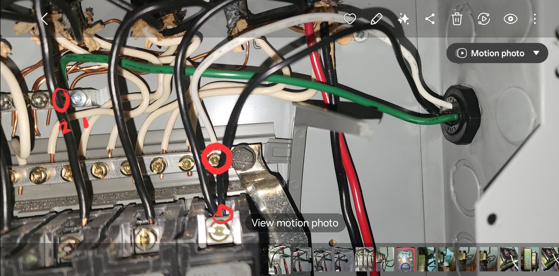
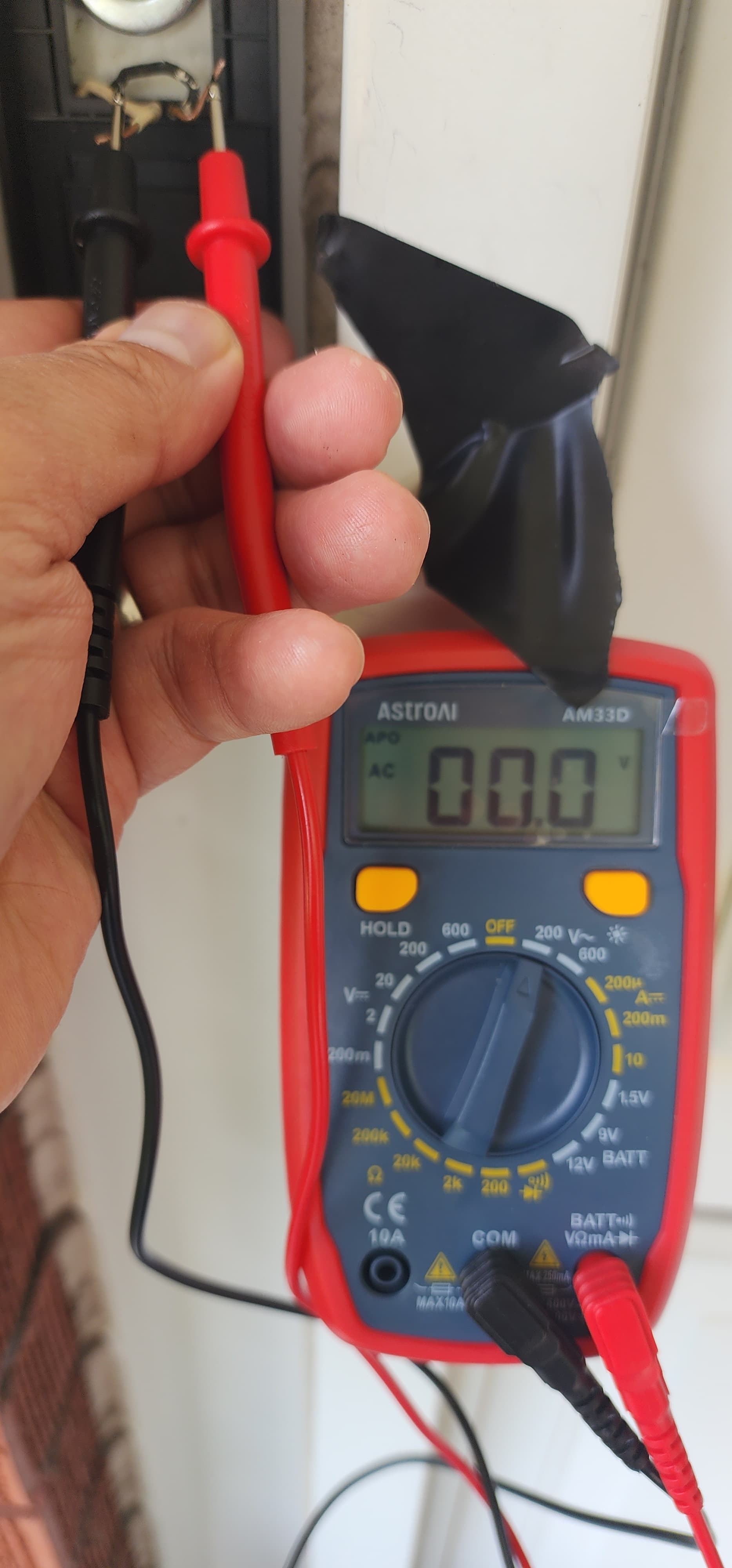
First, I’m curious about what and where you were measuring. What did you have the test leads attached to for each of the photos? The easiest and maybe best place to start might be the two wires that come out of the wall where you have your Duo Cam Doorbell mounted, because that’s where you really want to know if adequate power is being delivered. When you get ready to test, I’d disconnect the Duo Cam Doorbell entirely (uncouple from the screw terminals) so that you just have the two bare wire ends (or if you’re using extension wires then it’s okay to leave those connected so that your two spade terminals are free), one to touch to each of the multimeter’s probes.

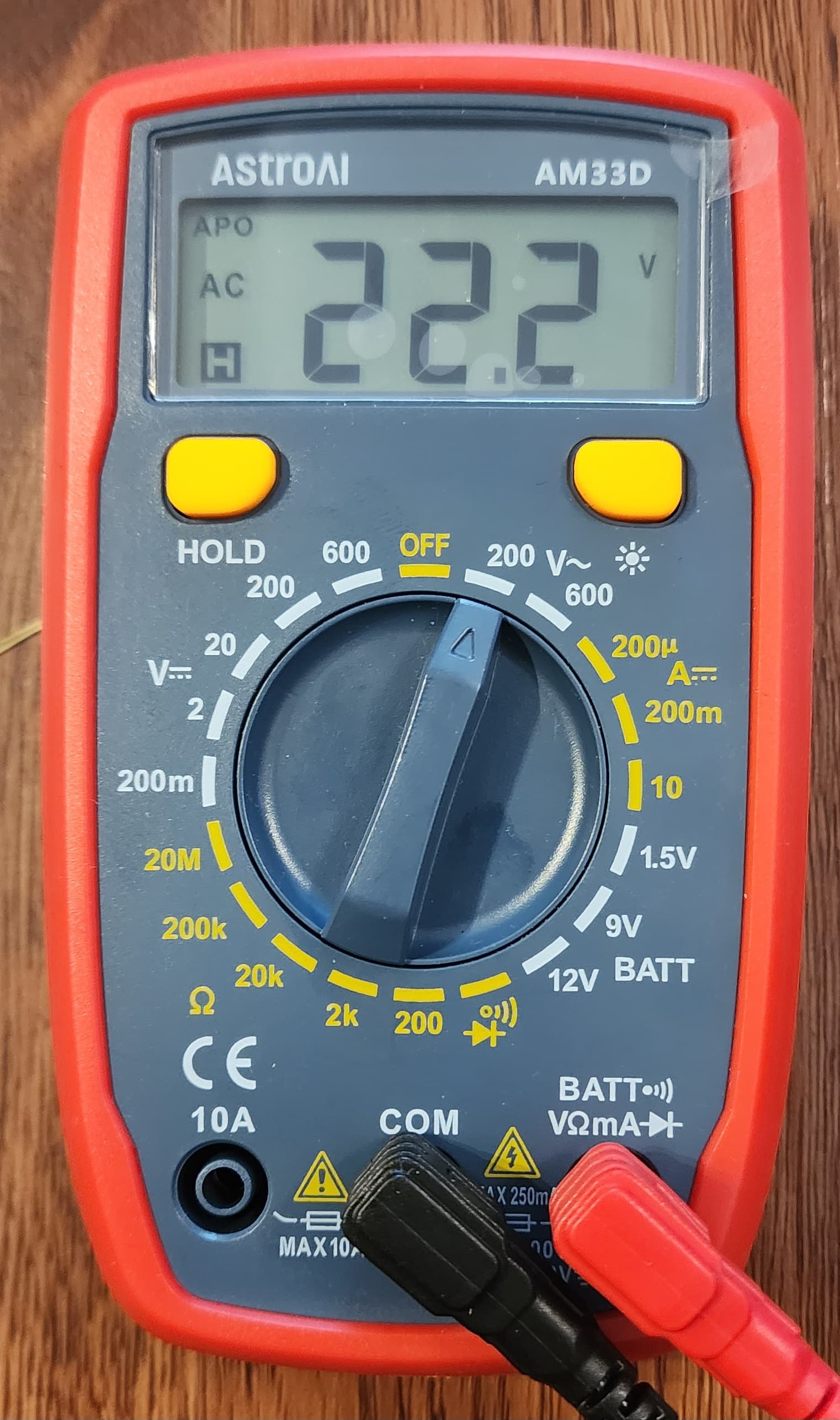
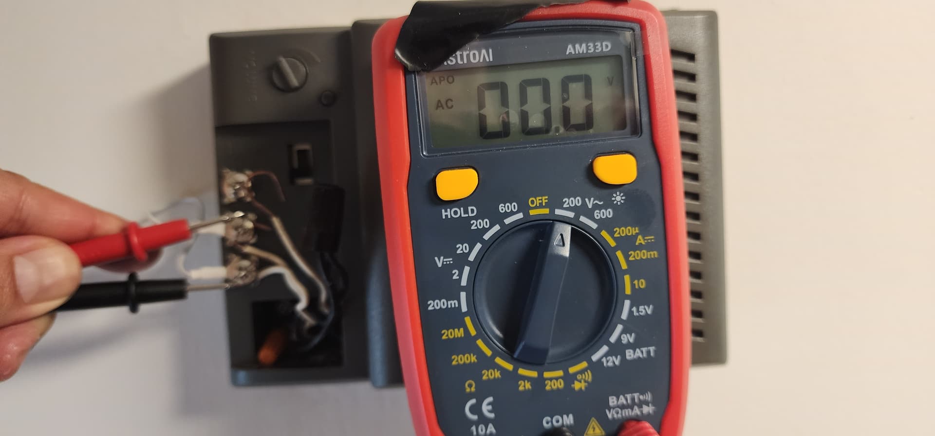
In your first photo, you have the multimeter set for DC voltage measurement (V⎓). In the second photo, you have the multimeter set for resistance measurement (Ω). Neither of those is what you want in this case. You want to know the potential of the low-voltage AC for powering your doorbell’s circuit, so you want to set your multimeter for AC voltage measurement (V⏦). I’ll get to that in more detail in a minute.

information Note:

When I pulled the PDF user manual for your meter and skimmed it, one of the things I read in the Measuring AC Voltage section was this:

If the AC setting is used to measure DC or vice versa, an overflow symbol will be displayed. Performing this action may damage the meter and any components you are attempting to test.

In this situation, I think your meter and the stuff you’re testing is probably okay, but it’s important to be aware of that note for the future. I didn’t see in the user manual for your device what the “overflow symbol” is supposed to look like on your LCD, so I’m still not quite sure what to look for there.

I’d also note that the instructions for my multimeter say this:

Warning: Never measure resistance on a circuit with voltage running through it.

I didn’t see that same kind of warning in your user manual, but I also didn’t read the whole thing. Maybe your multimeter has some kind of protection built into it to prevent damage if you test resistance on a live circuit? I just think this warning makes sense and is probably good advice in general.

For testing at your Duo Cam Doorbell’s wiring location, you want to set the multimeter’s dial in the V⏦ range—just clockwise from the “OFF” setting—for AC voltage measurement. On a circuit with unknown voltage, you’d normally start with the dial on the highest-range setting for whatever you want to test—600 V in this case—but you can just set it to 200 for this test. (If you’re testing a higher-voltage circuit [but less than 600 V] with the meter set at 600 and see a reading less than 200 on the display, then that’s when you’d step the meter down to the 200 setting for a more precise result.) Touch one of the multimeter’s probes to one of the conductors coming out of the wall and the other probe to the other wire. That’s where you want the meter to be showing you something in the 10-24 V or 16-24 V range (depending on which of Wyze’s sources you trust).
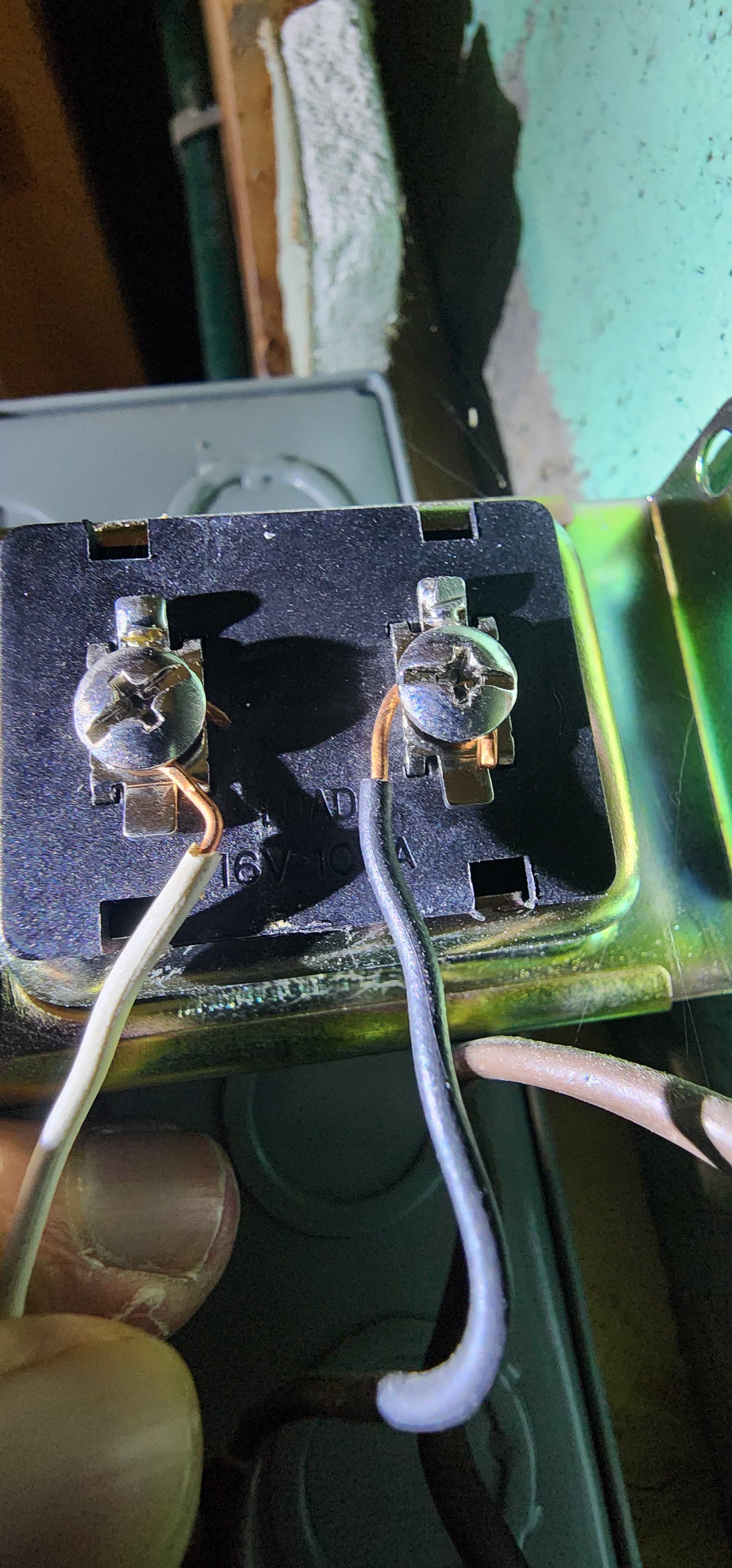
Excellent! :+1:

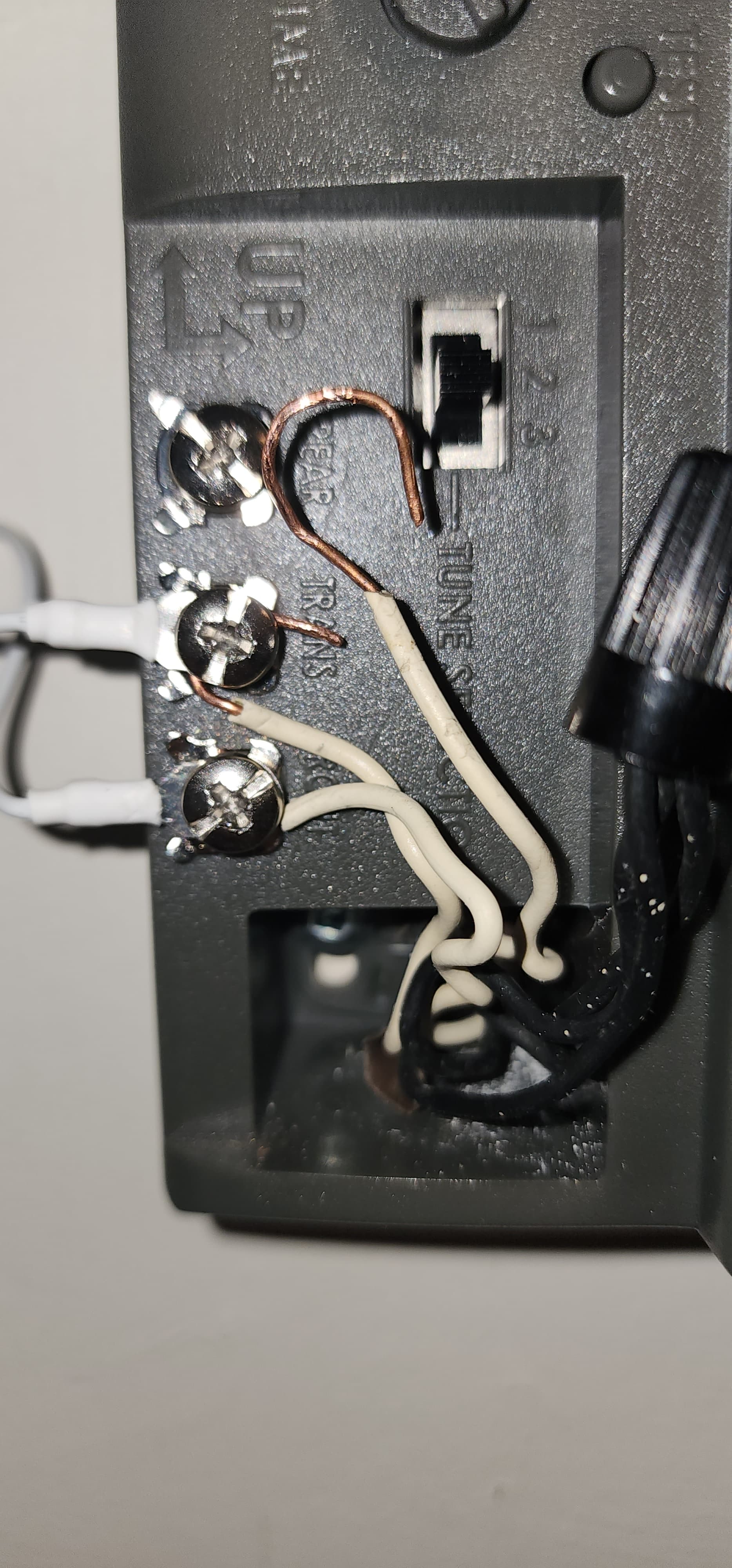
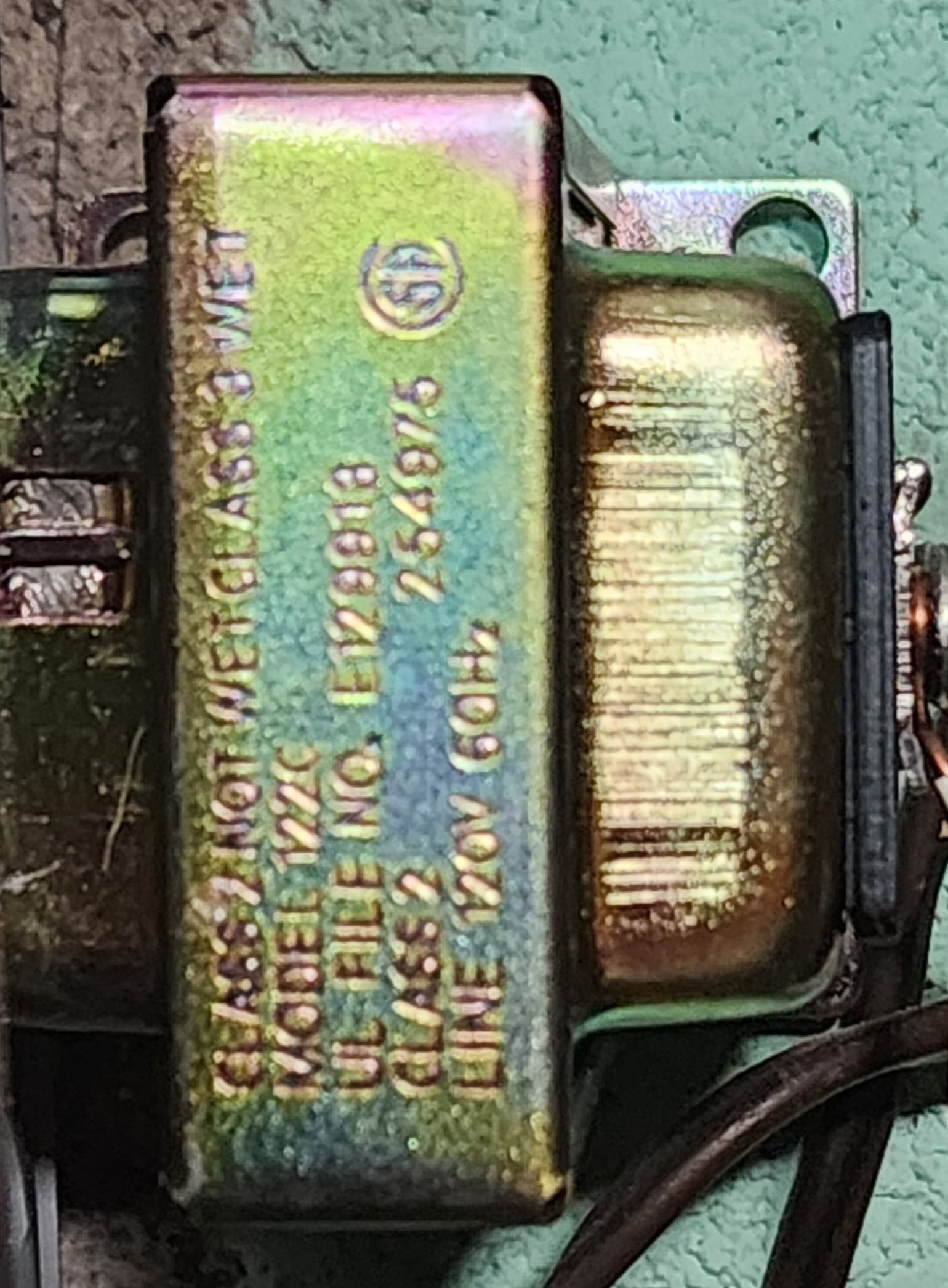
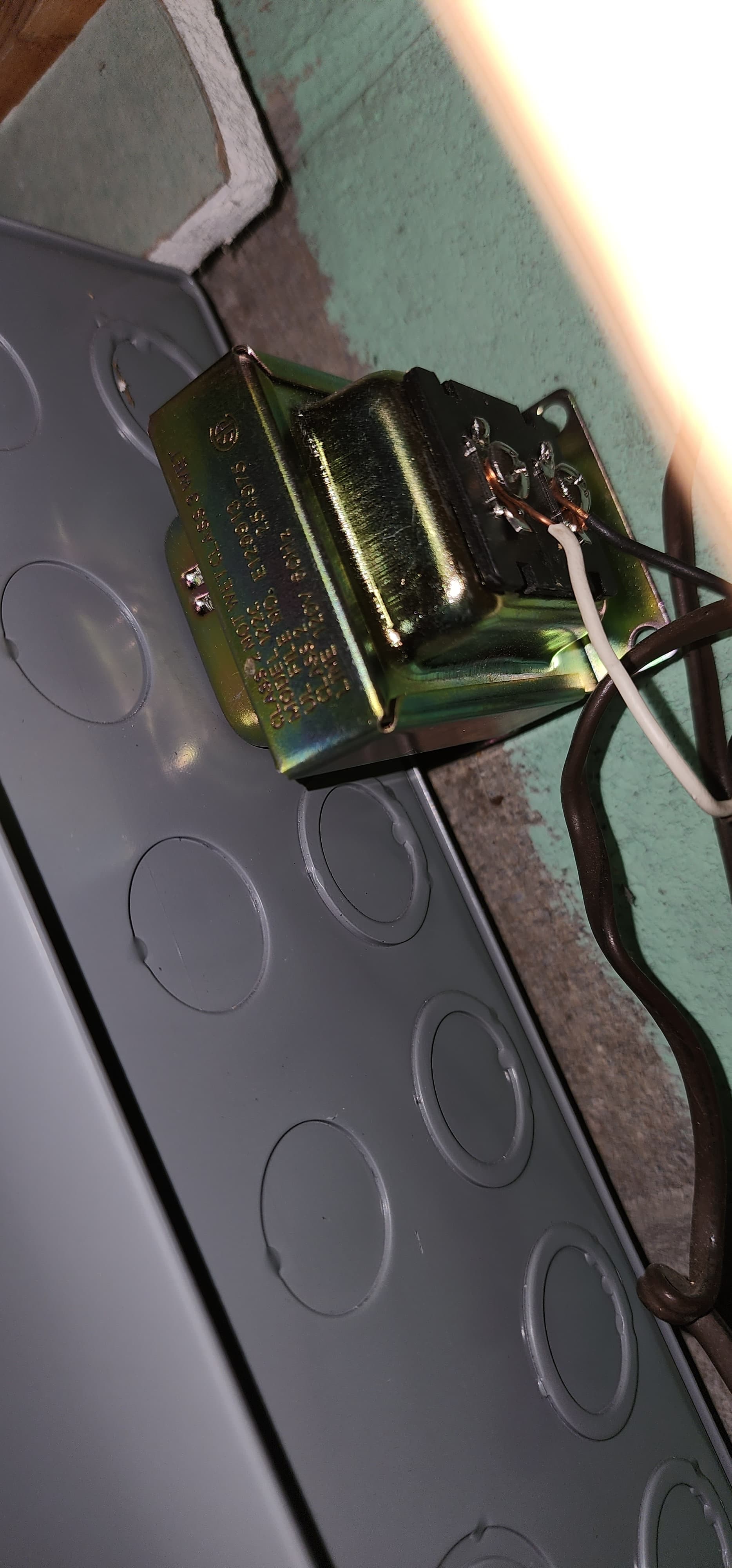
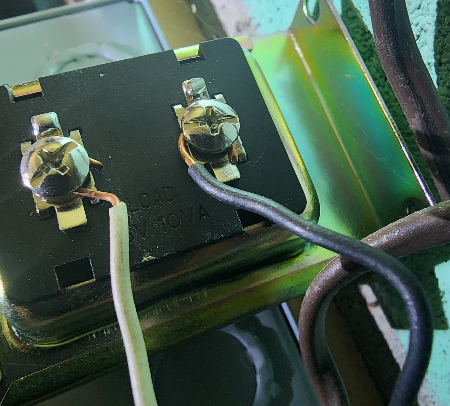
That looks right, because the black and white wiring jackets are what I would expect to see based on your previous chime photo. On the right side, where the screw terminals are, they’re backed by a black insulator plate which probably has the transformer’s output rating on it. What does that say? What I see when I do a search on the model number is this:

The 122C wired door chime transformer features a 120VAC input and 16VAC-10VA output.

It would be good to know what the output is supposed to be and then you can test it to see what your multimeter tells you, again using the same AC voltage settings as described above. The result should look something like this:

:point_up: This is what I see when hook my multimeter up to my transformer rated for 16VAC-10VA output. Note that I’m testing AC Voltage, so my dial is set to “ACV”; this corresponds to “V⏦” on your multimeter.

That shouldn’t be difficult if you’re careful, but let’s not get ahead of ourselves! Let’s do some proper measurements and get some more data first.

I hope this makes sense. Let me know what you find and/or what other questions you have.

1 Like

wow amazing youre so fast and detailed.

Im still trying to process stuff. Im an illustrator by trade… Im trying to learn all this.. totally out of my comfort zone.

ok. so here some new info.

I tried the multimeter again. i think this might be the right settings.

and I took a photo of the backplate of the transformer.
I had to stick my phone around the corner to see it.

It was such an awkward, dark postion.. i couldnt see it with my bare eyes.


1 Like

That’s helpful. I think that’s probably a “16” behind the white wire, which should be adequate.

The new multimeter photo looks good, too. You have the dial set where I’d expect this time. :+1: What were you testing in that photo? Did you have the multimeter probes on the transformer’s terminals, the doorbell mount location’s wires, or something else?

A cool thing I noticed about your meter is that you have a setting for continuity testing, and that’s something that would come in handy if you wanted or needed to trace the wires and assure yourself that the FRONT, TRANS, and REAR wires were properly connected in your chime box. That’s something that you can also test with the resistance (Ω) setting, but having a dedicated setting for that is handy, and it looks like that’s the setting you use when doing self-tests on the meter, per the manual.

I get that. I didn’t learn all at once, but I like learning and tinkering and trying to figure things out, and then I enjoy sharing what I’ve learned. I think it’s cool that you’re making an effort to do this yourself!

1 Like

i had to double check. it was 16!!
good eye.

i was taking the reading. from the transformer beside the circuit breaker.

I should try it at the doorbell again..I hope its not those wires itself thats messed up

1 Like

@Crease - Great job of tutoring, particularly with use of the multimeter. Took note of @kidchuckle’s transformer output at 22.2v surpassing spec’d 16v. Very good for a single db duo. If 2 duo’s connected at the chime box to ring the house chime, 16/10 may be problematic keeping both battery packs fully charged. I always recommend 24/40 for 2 duos activating house chime which has been very successful for my duel install. @kidchuckle disregard if only 1 duo.

1 Like

Thanks. That was partly based on what I was seeing and partly based on the specs I saw online, which I guess were correct. :grin:

That’s good to know, and I think that tells us that your transformer is probably in good shape and adequate to the task. I would put any thought of replacing that behind you for now, but since you watched some videos you can tuck that into your back pocket for the future and revisit that if needed.

I would definitely do that, because that’s what we really care about at this point as far as maintaining your Duo Cam Doorbell’s battery charge.

Good work! :+1:

Thanks! :+1:

Yeah Crease has gone above and beyond!!!

oh so a new transformer maybe needed?
yes I have a duo

thank you for your response


Ok I went and took of the duo. I thought since its off. I might as well recharge the battery again

I think there maybe something odd going on with my wiring.

with the multimeter. there is no reading.

I even tried pulling off the extension wires
( i tried to upload a video, but i had an error)
20250620_080403_1(1)

but with the ac voltage detector i do get a reading.

I did try the multimeter on the old chime box no readings.

but with the voltage detector there is a reading.

No, I’m saying exactly the opposite:

Your earlier photo that showed a test of your transformer’s voltage should be telling us that it’s okay. You can leave it alone for now, though depending on the kind of testing we do, you might be temporarily disconnecting those wires at some point. I don’t think you need to do anything there yet, though.

I think so, too, so that’s what we need to figure out next.

What does this mean, exactly? If you could test the wires where you removed the Duo Cam Doorbell with the multimeter at that same 200 V⏦ setting and share what the display says (or another photo would be even better), then that would be helpful. I’m interested in seeing if it just shows “0” or something else.

I’m not familiar with that particular voltage detector, so I’m not sure how to interpret the lights. I really like those non-contact voltage detectors for some things—especially when working with higher voltages—and have used similar pen-type voltage detectors to assist with tracing circuits and finding the “hot” wire in a particular box, but in a case like this what we’re really interested in is whether adequate voltage is being delivered to the location where you’re mounting your Duo Cam Doorbell. That’s why a multimeter is a better tool for this particular application and gives us better data (an actual number).

Besides, you should get as much use out of your new toy tool as you can, right?

What, specifically, were you testing there, and how were you testing? (Again, this is where I like having a set of test leads like I mentioned in my second post above, because it allows me to clip wires to things and have my hands free to take photos or manipulate the meter.)

I know that I ask a lot of questions and write a lot, but I’m trying to work my way through this problem in a way that makes sense to me (and I hope it makes sense to you; tell me if it doesn’t or if I need to be more clear about anything). I appreciate your patience with this.

i took a picture.

for some reason. nothing seemed to read.

and then again on the chime box.

sorry if I’m not clear.
I really appreciate your help!

Awesome! It’s zero. That’s not what we want to see there, but it’s good data.

Yeah, what’s happening in that second photo? You did something to the black wires, it looks like. I see what looks like an orange wire nut that wasn’t there before. Are all three of the black wires still connected together? That portion of the image is slightly out of focus, so I’m not sure.

No worries. The photos really help! :+1:

I have some ideas about how I would proceed at this point, but I’d like to know more about what’s happening with the chime wiring first.

One more question: When you’re doing these tests, do you start with the multimeter self test first? In the manual I found, it’s Step 2 under Measuring AC Voltage. You turn the dial to the position with the diode and sound symbols, near 6 o’clock, touch the leads together, and should hear a buzz. If that’s working as expected, then we’re probably going to use that in the next set of steps to trace your wiring. This’ll be fun. :grin:

(I sincerely hope that you’re not yet frustrated with the situation or with me. I enjoy problems like this and hope this is helpful. I really think you can do this as long as the wiring is all intact. We just need to know more about it.)

Yeah, I’m so sorry I’m horrible at describing this. It’s all new to me.

Oh, the black wires. I didn’t adjust them. just moved them. The orange cap.. it’s not in use. just there if I need at some point (at one point, I think I had twisted the two white wires together, and just used the jump cables. to see if it would make any difference.

Unfortunately, it didn’t do anything.

I’ll read up on that self-test and then try it out!

I am slightly frustrated. but I’m learning a lot and look forward to the responses. It’s really helping me a lot. I’m trying to learn to be a bit more handy… and this is out of my comfort zone.

the online manual is more detailed then the manual I recieved.

i guess it may have been too many pages.

I did the test. It seems to work
20250620_144027(1)

Also I went to the circuit breaker and tried to do a measure… and I was getting results still.
So frustrating.
It just seems like somewhere at the wyze cam there is no power getting there.