You’re doing good work, and the pictures are especially helpful! This was all new to me at one point, too.
Okay, good. We’re going to undo them.
NOT YET! I’ll give you specific steps of what I want you to try, but I want some more information first. Then I’ll walk you through what I’m thinking and hope it makes sense. Any time I’m not being clear or you have questions about anything, just stop and ask.
I understand. I’m not frustrated by this at all. This is a solvable problem. (I like these kinds of problems and am enjoying this.) If I can do anything to help with the frustration, then please let me know.
That’s part of what makes this so enjoyable for me: You have a willingness to learn, and I get to feel like I’m teaching something.
It looks like at the end it shows “OL”, which I guess must be the “overflow symbol” noted in the instructions. Does it beep when that happens? That’s what the manual says it should do in that situation.
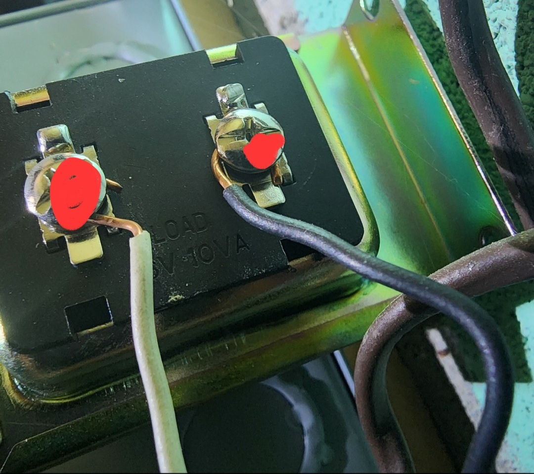
What did you do there? I’d be especially careful in that area, because it’s higher-voltage (~110-120 V AC) stuff. Everything we want to work on at this point is downstream from the transformer, which we’ve tested and believe to be good. Its job is to step the current down from that higher household range to the low-voltage (let’s say 16-24 V AC) range so we can deliver the expected power to the doorbell without zapping it.
If you know which breaker controls your transformer, then I might have you temporarily switch that off at some point so we can test and trace the wiring. Other than that, I don’t want to mess around in the breaker box.
Yup. We’ll figure that out. I’ll get to that when I have answers to the previous questions in this post.
Okay, good. And you were still seeing 22.2 V AC or something close to that?
What about this other question?
I want to make sure the multimeter is doing what it’s supposed to be doing when you have it in continuity testing mode, because that’s how I want to try to trace the wires. (When I traced mine, I used my meter’s resistance testing mode, but since your meter has one specifically for continuity testing that provides audible feedback, let’s use that.) I want to know that it’s working as expected before we (you) proceed.
Rather than waiting for your answers to the previous questions and then making you wait until I post a reply, I’m going to go ahead and post this now with two caveats:
It’s long. I tried to be detailed and explicit so that there’s minimal ambiguity, but if you have questions at any time, then please stop and ask.
It presumes that your multimeter’s Continuity Test mode is working as expected, so proceed only if that is the case. If it isn’t, then please let me know and we can come up with a different plan.
Ready…?
I’m not, so I hope you’ll forgive the crude diagrams. This is what I believe we’re dealing with in terms of the way your wiring was—or should have been, which is what we’re going to try to determine—before you wired in the Duo Cam Doorbell:
There should be a pair of conductors—one wire with white insulation and one wire with black insulation—for each device that’s meeting at the chime, so the chime is kind of like a junction box. The black wires are all connected as a common conductor for the circuit. The white wires are connecting individual components to separate terminals on the chime. What we want to know is which pair of wires is connected to which endpoint and if they’re intact. This is what I’d do:
Get something to label the wires at the chime. I tend to use blue painter’s tape and a black Sharpie. You get what’s convenient and works for you.
Turn off power to the transformer at the breaker. You can use your non-contact voltage tester and/or multimeter in AC Voltage (V⏦) mode to test the transformer and make sure it’s off. The multimeter should read “0” (probably more like “00.0”) when you test.
Disconnect one of the wires from the transformer. It doesn’t matter if you choose black or white. We just want to create an air gap in this part of the circuit so that one of the wires is not touching another conductor. You don’t need to cap it (but you can do that or throw a piece of tape on it if you want). This is temporary. Just make sure one wire end is free and not touching anything but air.
Go to the rear doorbell button’s location. Disconnect one of the wires from the rear doorbell button to create another air gap. This might not be necessary, because the switch should be open when the button isn’t being pressed, but disconnecting the wire can give us confirmation that we’re going to have only one closed loop at a time for each part of this test. Again, you don’t need to cap it, but you can if you want.
Go to the front doorbell button’s location. Connect the two wires that you plan to use for the Duo Cam Doorbell power. This will be a temporary connection, so even holding them together with an alligator clip should work. We just need the metal parts of the wire to be touching and have good contact with each other and nothing else. What we’re trying to do is create a continuous conductive path from one of the white wires at the chime out through this connection and then back through one of the black wires.
Go to the chime’s location. At the chime, you can label the white wires if you want to keep track of their original positions (FRONT, TRANS, REAR), but we might be changing those at some point, so this step is optional.
Remove the nut from the three black wires and separate those so that no conductors are touching. You don’t have to label them (you can if you want), but we’re going to be referring to them temporarily as Black1, Black2, and Black3.
Since your “REAR” white wire is already disconnected (“free”), we’ll start with that one. Put the multimeter into Continuity Test mode.
a. Touch the multimeter’s probes together to confirm that it beeps and is working.
b. Touch one probe to the free white wire and the other probe to Black1. If the multimeter beeps to indicate continuity at any time during this step, then STOP! Label both of these wires (one black and one white) as FRONT, move them out of the way, and skip to Step 9.
c. If there was no continuity with Black1, then repeat Step 8b with the free white wire and Black2.
d. If there was no continuity with Black2, then repeat Step 8b with the free white wire and Black3.
e. If there was no continuity between the free white wire and any of the black wires, then we need try a different white wire. Move the original free white wire out of the way. (This is where painter’s tape can be handy to temporarily “cap” something as a marker, too, to let you know not to use that one for now.) Disconnect the white wire from the TRANS terminal and go back to Step 8b, repeating the test with each black wire and this new free white wire. Again, if at any time you get a continuity beep from the multimeter, then STOP! Label those two wires as FRONT, and go to Step 9.
f. If there was no continuity between this second free white wire and any of the black wires, then set this second white wire aside, disconnect the white wire from the FRONT terminal, and go back to Step 8b.
g. If there was no continuity at any time during this step—each of the white wires was tested against each of the black wires, but you saw or heard no continuity indicator—then verify the air gaps at the transformer and rear doorbell button and also verify that the two wires at the front doorbell button location have a good connection to one another. Then go back to the beginning of Step 8 and try again. If you’re sure you did everything right and still got no continuity signal, then the wires to the front doorbell location may not be intact, so you could stop the project or contact an electrician for assistance. Skip to Step 20.
Since we created air gaps at both the transformer and rear doorbell button and made sure the two wires at the front doorbell location were connected (closed the loop), if we got continuity with our test at this point, then the signal must be going through that front location, so now we know that part of the wiring is intact. You can uncouple those wires at that location because now we want them to be free and disconnected (make sure they’re separated and not touching anything; capping each individually is optional).
Go to the rear doorbell button’s location and connect those two wires together. Again, you could use a metal alligator clip or even screw them both to the same terminal on the back of the button. We just need the conductors to be touching to test this loop for continuity as we isolate and determine the elements of your wiring layout.
Go back to the chime, where you previously labeled one black and one white wire as FRONT. These are no longer “free”.
a. Pick one of the remaining free white wires and test it for continuity (multimeter in Continuity Test mode) against one of the free black wires. If at any time in this step you get a continuity signal from the multimeter, then STOP! Label those two wires as REAR, and skip to Step 12.
b. If the first black wire fails, then test this same white wire against the other black wire.
c. If testing fails with the first free white wire, then switch to the other free white wire and test it against each free black wire.
d. If none of these 4 combinations indicates continuity, then check the wires at the rear doorbell again—make sure they’re connected—and repeat Step 11. If all continuity checks in this step fail a second time, then skip to Step 20.
Go back to the rear doorbell button’s location and reconnect it the way it was before you started (one wire on each screw terminal). We’re done with this location.
Go back to the chime. You should still have two “free” wires, one black and one white. Label these as TRANS. Make sure no two wires are touching any other conductors (including other wires). All six wires should be labeled and separated.
Go back to the transformer. Reconnect the wire you disconnected before. Turn the breaker on. Switch the multimeter to AC Voltage (V⏦) mode and test the transformer. This should once again read 22.2 V AC (or very close to it).
Go back to the chime. Again with multimeter in AC Voltage (V⏦) mode (this is the mode we’re using for the remainder of the steps), test the voltage between the two TRANS wires. This should also be in the 16-24 V AC range.
Go back to the breaker box and turn off the transformer’s breaker.
Go back to the chime. Reconnect the black wires together with the wire nut. Confirm that all of the conductors are touching when you insert them into the nut and give each a little tug once the nut is on to ensure a good connection. Connect the TRANS white wire to the TRANS terminal and FRONT white wire to the FRONT terminal. Make sure the jumper wire is connecting those two terminals, as well. Cap the REAR white wire with a wire nut. (You can use your orange nut, because you were thinking ahead! ) Now your wiring diagram should look like this:
Go back to the breaker box and turn on the transformer’s breaker.
Go to the front doorbell location and test the voltage (multimeter in AC Voltage (V⏦) mode) of the wires that you want to connect to your Duo Cam Doorbell. This should also be in the 16-24 V AC range. If it is, then you can set the multimeter’s mode to OFF and skip to Step 21.
You got to this step because there was a continuity or other failure at some point, in which case you can stop the project or contact an electrician for assistance. If you haven’t already done so by this point, you can also reconnect the rear doorbell button and transformer as they were before you started, nut together the black wires at the chime as before, and leave the white wires free. Then come back here and let me know what went wrong. Skip to the next non-numbered section (skip Steps 21-25).
Go back to the breaker box and turn off the transformer’s breaker.
Go back to the front doorbell location. Connect the wires to the Duo Cam Doorbell’s screw terminals (it doesn’t matter which wire goes to which terminal), and mount the doorbell.
Go back to the breaker box and turn on the transformer’s breaker.
Check the Duo Cam Doorbell in the Wyze app to see if it shows any indication of charging or battery level (I’m not sure what it’s supposed to show).
Be less frustrated and enjoy the successful completion of this project!
Hopefully that all makes sense and works out. If at any time you have questions, then please don’t hesitate to reach out with those. If anything doesn’t seem right at any point in the process, then please feel free to stop and let me know.
I really think you can do this, and I look forward to reading about your success!
2025-06-21T04:32:11Z Edit: I changed the instructions slightly and added a second wiring diagram. 2025-06-21T13:39:30Z Edit: I added a few more details for clarity. 2025-06-22T04:06:07Z Edit: I added <mark></mark> tags to highlight the necessary multimeter mode setting for a given test/section.
wow thanks so much.
I didnt have a chance to look through your post until the fam went to bed.
I will probably be able to work on this monday.
I had once had the multimeter beep. but I dont think the last time I did it… it beeped. but I think maybe the battery maybe running low.
but it did go to 22.
I should have more time monday and during the week to mess around.
You’re welcome, and thanks for taking the time to post an update!
It’s long, but I think the steps are all correct. If you can follow those and things test out the way I anticipate (again, as long as your wiring is actually intact in the way we think it should be), then I think you’ll be able to do this and get power to your Duo Cam Doorbell at the front location.
Those should be two different modes, I think, so I’m trying to be clear about that (at least as I understand your particular multimeter):
When you have the meter set to Continuity Test mode (dial position with the diode and sound symbols just shy of 6 o’clock), then a successful test should result in a beep. That means that current is flowing from one probe out through whatever wire(s) you’re testing and back to the other probe. That’s how we figure out which pair of wires loops out to which endpoint (transformer, front button location, rear button location) and back if all the wiring is intact. I’m not sure what the LCD is supposed to show in that case, because I didn’t see that in the manual.
When you have the meter set to AC Voltage (V⏦) mode (the 200 notch just past 12 o’clock on the dial), that’s when we expect to see a number >16 (and you’ve been getting ~22, which I think is okay). I don’t think the multimeter is supposed to beep on this setting. If it is, then I missed that in the manual.
We need to use both modes—different modes at different stages of testing—to figure out your wiring situation, so it’s important to note which mode the instructions say to use at any given time. I’ll go back through the instructions after I post this to confirm, but I think I got that part right the first time. I’ll also mark the mode like this so you know how to set the meter at any given point during testing. If the instructions don’t tell you to change the mode, then use the last setting given in the instructions. (You can turn it to the “OFF” setting between tests if you want. Just remember to go back to the previous mode unless the instructions tell you to use a different mode.)
Just remember it’s a multimeter because it’s allowing you to test more than one thing, and we’ll be testing two things at different times:
Continuity = beep
Voltage = number
That’s cool. Just take your time and ask questions as needed. If my terminology is unclear at any point, then feel free to stop and ask me to explain something in a different way. I’d like to see you get this working, especially since you’ve described being frustrated. I really think you can get this done.
Sorry it’s been a little slow at replying. I had a few things for work to get out of the way.
But now the multimeter seems to work more consistently since I changed the batteries. I’m going to try to go over things today and tomorrow.
Sorry it’s not much of an update yet.
I really appreciate your help!
Ahh I think I understanding your thinking. You’re just isolating the wires step by step and testing them and organizing it!
I’ll give a follow up as soon as I can.
No apology is necessary. I’m just trying to provide some assistance and ideas, and you can deal with those on your own time.
Kind of, yeah. The approach I suggested should let you work on one pair of wires at a time, essentially joining that pair into one long conductor, so that you can determine continuity and have an idea of how your wires actually trace out. In the process of doing that, it should also help us learn whether or not there are any interruptions in the wires themselves. This should help you to actually know that the wires connecting to things at the chime are what we think they should be.
Again—and I probably sound like a broken record with this—it’s important to use the proper multimeter mode at the proper time while testing, so I hope that going back to the steps and marking certain things helps with that.
Were you ever able to make any progress with this? It’s no sweat if you haven’t been able to. I’ve been busy with other things, too, but I wanted to check in to see if you’ve had the opportunity to test and/or learn anything new.