Continuing the discussion from Calculating 3d cone of camera vision:
Below are some pictures showing how I took a 3D solid of a new style of window-mounted custom-aimed glare shield for V3 pro that incorporates a square pyramidal flare. This is to reduce or eliminate field-of-view restrictions experienced with some of the Sq Tube-type window mounts.
This is the wireframe representation of the new style of window-mounted V3 Pro camera holder.
the procedure for making this printable 3D solid is a topic in itself for a later time.
Below is a depiction of mapping the edge lengths of the solid to the z-plane to make a foldable model to check out on a window.
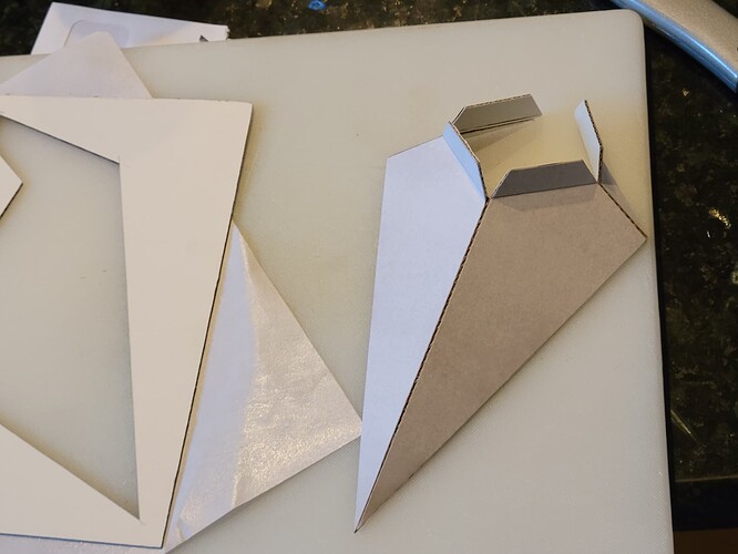
These next 5 pictures depict making the folded model.
These are old fashion draftsmen spline weights. Fishing weights or tire weights or steel bolts could be used instead.
Filling in the open corners.
These last two pictures show it taped to the window and the camera’s field of view.
Good view no restrictions.
Victor.
10 Likes
Outstanding post Victor. An excellent project and very much needed….tlhutch4
Thanks Tom.
I have improved some of the wording, added annotations to most of the pictures, and added another picture. I’m thinking about adding more detailed examples of mapping.
Waiting on my 3D printer.
Victor
1 Like
Very cool idea and execution. You could make a more durable, long term solution using a thin sheet of black kydex. Just as you did yours, trace the outline onto the kydex and use a heat gun and some wood or metal to make the sharp creases. Then you could create a tight seal around the camera using some gaffers tape or black rtv.
2 Likes
Hello @Vinnyg954 @tlhutch4 and All.
I have never heard of Kydex and rtv, After looking them up, they would be excellent materials for the folded crafts version of a window-mounted custom-aimed pyramidal shield camera holder. Thanks for the information. The purpose of the folded paper one I posted was to check out the camera’s view before committing to printing it. It took me 2.5 hours to print, cut, fold, and tape it together. The 3D print version will take over 8 hours to print.
For the fold-your-own people. I am trying to set up a spreadsheet to generate the mapping edge distances for a combination of user-picked aim angles. Your material ideas and the spreadsheet would be a good pairing.
Victor.
2 Likes
Theoretically you could create a “pyramid” with an open top and the camera would be situated in a sphere that mated to the pyramid top. Like a pyramid with a ball joint on the top. That would allow the end user to adjust the angle as necessary. But it would probably be a bit of an eyesore and unsightly to some. But that’s usually how it goes with universal devices. 3D printed would definitely be the way to go for those with access.
1 Like
Hello @Vinnyg954, @tlhutch4, @BillyCroan, and All.
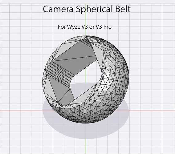
That is a heck of an idea Vinng954. It would replace the need for a table of edge dimensions for specific pairs of aim angles and all of the associated craftwork. It would eliminate the need for dozens of STL files for aim angle pairs for the 3D-printed plastic version of the paper version. I had envisioned a U-joint version for two degrees of aim adjustments, it would have been very clunky looking. Based on your idea I would use a truncated hollow cone with an incorporated window mounting flange that would be taped to the window. The truncated small end of the cone would have a ring with a concave inner surface to receive the camera. The camera would be fitted with a plastic belt, and the inner surface of the belt would fit the camera’s face cross-section. The outer face would be a spherical shape that would snap into the receiving ring of the cone. If 8 or 16 equally spaced narrow slits are radially placed around the receiving ring. One or more rubber bands could be mounted on the receiving ring to provide clamping force on the fitted camera belt.
Below are two drawings of the two moving parts of your idea with my alterations. The Receiving Cone is not complete, it needs 6 to 8 slits around the receiving flare to allow the snap-in of the Camera Belt.
I think this could look pretty clean and simple. However, after spending the time to draw this up, this version does not have enough angle adjustment. To get enough adjustment the camera belt diameter would need to be increased by 100% and the cone’s diameters increased accordingly. Also changing the cone to a pyramid would probably help.
If I make any I will send you one.
Victor.
3 Likes
The ideas keep improving with input from Victors original posting…Tlhutch4
1 Like
Dude, this is awesome! I hope you realize how happy this has made me. I have always been an idea guy able to conceptualize things in my head, and to articulate them to other folks. I’m a problem solver, and tinkerer. I love the tech like 3d printers, and micro controllers, but was never one to get into high end modelling or programming. I like to modify existing things, and I never would have been able to create something like you have in your above post unless I found something that exists already, and could modify for use, so thank you. I realize we’re working towards the same goal, but it truly it amazing to have been inspired by your idea, pass along my thoughts and then to see you have modeled up something from my brain. It’s almost bringing a tear to my eye. Really, @victormaletic thank you.
Also, my main thoughts on the pyramid we’re that a “square” base would be easier to mount on a typically square window, lining up with the edge would be easier. Also if one of the faces on the pyramid was longer (rectangular base vs. square) this would solve your angle adjustment dilemma. I’m picturing more of an Oblique Pyramid. You would then angle the camera towards the longer side. This should be a viable solution because you only ever need the camera pointing at one specific zone, and if it were a right pyramid, whatever faces of the pyramid we’re out of frame would just be wasted space. Although the right pyramid shape would allow for on the fly adjustments without remounting the main frame for a new angle. I.e. looking left, and now you want the camera to look right. With the right pyramid, you just adjust the belt in the socket. With the oblique pyramid you remove the frame, rotate 180 degrees, remount, and adjust the ball and socket. So I guess it just depends on the shape that works best for your case.
Hello @Vinnyg954, @tlhutch4 and All.
Vinntg954 your pyramid ideas are doable. The closer the camera is to the window the smaller the size pyramid required, hence the less material required and of course a smaller mounting area needed on the window.
My earliest window-mounted versions utilized one corner of the camera’s face touching the window. See the pictures below.
A folded cardboard version, with a very small window footprint but with a narrow field of view.
This group of pictures depicts how the Sq Tube window angle affects field of view restrictions.
With this Kite version, a wider field of view would require a more elongated footprint. Other aim angles require a different cut pattern.
An early 3D-printed version. Compact, different aims require different prints, Field of view is constrained by the tube-shaped shield. Using a custom-aimed pyramid instead of the tube would allow wider camera field of views.
An early adjustable version. Somewhat clunky looking, but it can be adjusted and aimed in any direction. A cardboard box of suitable dimensions could hide it and serve as a backlight shield
A more recent adjustable box shield setup. The size of the box determines the allowable aim angles. It also takes up more window area. Also requires some building skills.
I have a dozen outside types of mounts you may be interested in on the forum. Search Victor and camera mounts, brackets, or supports.
With shielded window mounts, I haven’t decided which direction to take.
Victor.
3 Likes


